
 EN
EN
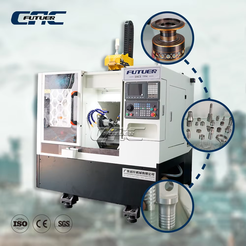
G-Code Syntax and Modal Behavior Pitfalls in Syntec Lathe Programming
Modal G‑code—commands that stay active until explicitly changed—streamlines program length but introduces subtle hazards on Syntec lathe controllers. Misapplied modality causes coordinate drift, unintended tool paths, and silent deviations that waste material and time.
Incremental vs. absolute mode confusion and coordinate system misalignment
A common error is mixing G90 (absolute) and G91 (incremental) without clear modal awareness. On a Syntec lathe, the active positioning mode persists across blocks and even after program restarts if not reset by a safety line. Programmers who assume a power‑up default to absolute may run a block of incremental moves, shifting the work zero without warning—leading to tool crashes into the chuck or oversized parts. Always insert an explicit G90 or G91 at the top of every tool path and after any canned cycle. Anchor the datum with a consistent coordinate system call (G54–G59). A single missing G90 in a finishing pass can scrap a batch—rework costs often exceed $2,000 per incident in prototype shops.
Missing end‑of‑block delimiters and unintended tool path loops
Syntec controllers interpret a missing semicolon or line‑feed as a run‑on block, merging two operations into one sweeping motion. When a block lacks its end delimiter, the controller may loop the preceding modal command indefinitely—or until a hard limit trips. For example, a forgotten semicolon after G01 X50.0 F0.2 might cause the tool to keep feeding at 0.2 mm/rev until it hits an overtravel switch. Night‑shift operators miss these errors because the machine does not always alarm; the path simply deviates. Always proofread code with a text editor that shows invisible characters, and set the controller’s block‑buffer display to verify each block ends with a recognized terminator. Formal code reviews reduce such syntax flaws by nearly 40%, per an internal audit by a leading machine tool builder.
Why Syntec’s modal G‑code logic differs from Fanuc/Heidenhain — and how it causes silent path deviations
Syntec lathe firmware handles modal retention differently than Fanuc or Heidenhain, creating “silent” deviations when programs are ported without adjustment. Unlike many Fanuc controls that reset most G‑codes to a defined safe state after M30 or Reset, Syntec often preserves the last active G‑code in memory. A cycle ending in G91 (incremental) may restart in that mode, shifting subsequent absolute moves. Heidenhain users accustomed to automatic plane‑specific modality—e.g., G18 automatically cancelling tool radius compensation in the ZX plane—find Syntec requires explicit cancels. The table below highlights critical modal‑behavior contrasts.
| Feature | Fanuc (typical lathe) | Heidenhain (TNC) | Syntec (lathe) | Silent‑deviation risk |
|---|---|---|---|---|
| G90/G91 reset after M30 | Defaults to G90 | Retains last mode | Retains last mode | Incremental restart causes datum shift |
| Cutter comp (G41/G42) off | G40 activated by reset | Must cancel explicitly | Must cancel explicitly | Tool radius applied without warning |
| Plane‑specific modality | Rarely plane‑bound | G18 cancels TRC | No automatic linking | Offset remains active when plane changes |
To avoid these pitfalls, always build a robust startup block (e.g., G18 G90 G40 G80) at every tool call. Simulate programs with syntax‑aware verification software, and never rely on controller defaults after a program stop.
Tool Radius Compensation (TRC) Errors on Syntec Lathe Systems
D-code mismatches and inconsistent tool geometry offset registration
On a Syntec lathe, D‑code mismatches are a primary source of TRC failure. The D‑code selects the tool radius offset register; if it does not correspond to the active tool number, the control compensates with an incorrect radius. This often happens when programmers copy and paste tool path segments without updating the D‑value. Inconsistent geometry offset registration compounds the problem—an operator may enter a tool’s length or radius into the wrong offset field, or the wear offset table may contain residual values from previous measurements. The result is a contour that is either over‑ or under‑sized, often detected only after the part is scrapped. Verification requires cross‑checking the D‑code in the program against the offset table. Some integrators enforce a rule that the D‑number must match the tool number, eliminating ambiguity.
Premature or delayed G41/G42 activation causing gouging or under-cutting
G41 (left compensation) and G42 (right compensation) must be activated on a linear lead‑in move of at least the tool radius. If the activation block is too short, the control cannot fully engage the offset before the contour begins, leaving a gouge. Conversely, if compensation is applied too early—within a clearance move that is not a straight line—the tool path may curve unexpectedly, under‑cutting the profile. On Syntec controls, look‑ahead logic processes several blocks ahead, so a premature activation inside a rapid traverse or arc often triggers a path deviation without an alarm. The fix is to insert a dedicated approach line of sufficient length—typically 1.5 times the tool radius—and to cancel compensation (G40) on a similar straight retract move. Verifying the programmed path with the control’s graphic simulation before cutting is the safest practice.
Spindle and Feed Rate Configuration Mistakes in Syntec Lathe Programs
S- and F-value Errors from mm/min vs. mm/rev Unit Mode Misconfiguration
One frequent spindle/feed error on Syntec lathes arises from confusion between G94 (feed/min) and G95 (feed/rev). A programmer intending 0.2 mm/rev for turning—but with the machine still in G94 from a prior drilling cycle—forces the controller to interpret F0.2 as 0.2 mm/min. The mismatch often goes undetected because axes still move, but the feed rate is orders of magnitude off. At 1000 RPM, 0.2 mm/rev equals 200 mm/min; in G94, 0.2 mm/min is 1000× slower—turning the cut into a burnishing operation that work‑hardens the material and dulls the insert. Conversely, applying a roughing feed of 0.5 mm/rev as 0.5 mm/min risks aggressive dig-in and tool breakage. Because Syntec defaults to G95 at power‑on but any G94 command persists modally, explicitly insert G95 at the start of each tool path and verify the S‑value aligns with the material’s recommended surface speed.
Syntec-Specific Alarm Diagnosis and Root-Cause Triage
Interpreting critical Syntec alarm groups: 01xx (motion), 03xx (program), and 05xx (I/O)
On a Syntec lathe, alarm codes are grouped by subsystem, enabling rapid triage. The 01xx series flags motion faults—axis overtravel, servo drive errors, or excessive following error—directing attention to the mechanical drive or feedback loop. When a 03xx alarm appears, the root cause almost always lies in program syntax: an illegal G‑code, missing end‑of‑block delimiter, or modal conflict. The 05xx group covers I/O signals, including emergency stop activation, limit switch triggering, and pneumatic pressure loss. Recognizing the group instantly narrows the diagnostic scope; technicians report this classification cuts troubleshooting time in half by moving straight to the relevant subsystem instead of guessing.
Using trace logs and alarm context to distinguish programming errors from operator or hardware faults
The same alarm code can stem from a software bug, hardware glitch, or operator misstep—but the context captured in the trace log reveals the difference. Search for the alarm in the log and examine the preceding ten lines: if the error repeats at the identical program line across multiple runs, it is a programming error. If it appears sporadically—or only after a tool change—suspect a loose I/O connector or worn limit switch. Compare the commanded position from the G‑code with the actual axis feedback logged by the Syntec lathe’s servo trace: a consistent drift points to hardware degradation, while a sudden jump suggests operator interference or an unplanned stop. This systematic log correlation isolates the true root cause without trial‑and‑error component swaps.
FAQ
What is modal G-code?
Modal G-code commands remain active until another command overrides them. These are used to simplify programs but require careful configuration to avoid errors.
Why is the G90/G91 switch important?
Mixing G90 (absolute mode) and G91 (incremental mode) improperly can cause unexpected tool crashes, oversized parts, or work coordinate shifts.
How do Syntec lathe controllers differ from Fanuc in handling modal G-code?
Syntec controllers retain the last active mode after program reset, unlike Fanuc, which typically defaults back to safe states.
What is tool radius compensation (TRC)?
Tool Radius Compensation adjusts the tool path to account for the tool’s geometry, ensuring accurate contouring of the part.
How can spindle-feed errors arise?
Errors can occur due to mix-ups between units like mm/rev and mm/min. Always specify G94 or G95 explicitly to prevent misconfiguration.
How can alarms on Syntec be debugged?
Syntec alarms are grouped by subsystem, enabling targeted triage. Context from trace logs can help pinpoint whether errors stem from programming, hardware, or operator actions.