
Understanding CNC Turning Centers: Function and Core Mechanics
Definition and Core Purpose of a CNC Turning Center
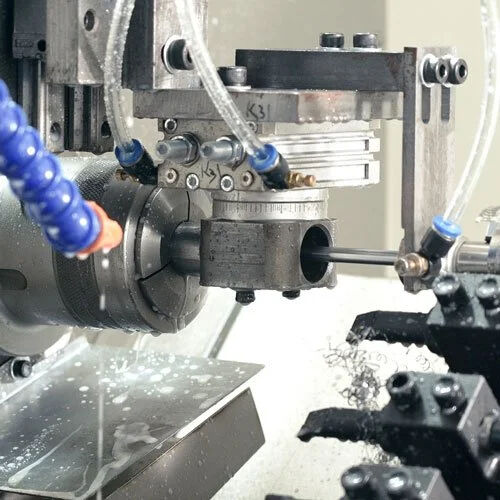
CNC turning centers represent computer controlled machining systems that excel at shaping cylindrical components with exceptional accuracy. These machines differ from traditional manual lathes because they handle all the rotational cutting work automatically based on pre-programmed instructions. Industries where precise measurements matter most find these systems absolutely essential. Think about sectors like aerospace engineering, car manufacturing plants, or even companies producing intricate medical devices. At heart, what these machines do is transform basic materials such as steel bars, aluminum stock, and sometimes even tough metals like titanium into complicated shapes by removing material bit by bit. Big name manufacturers across various fields depend heavily on CNC turning technology for both quick prototype development and mass production runs since the machines can repeat tasks exactly the same way every single time while minimizing mistakes made by human operators.
Working Principle of CNC Turning: Rotation, Toolpath, and Automation
The working principle hinges on three key elements:
- Rotation: The workpiece spins at speeds up to 6,000 RPM while stationary or live tools remove material.
- Toolpath Automation: Pre-programmed G-code dictates tool movements along X and Z axes, enabling operations like facing and grooving.
- Closed-Loop Control: Sensors monitor torque and deflection, adjusting parameters in real time for optimal surface finish.
This synergy ensures precision down to ±0.0005 inches (12.7 µm), even for intricate features like threads and knurls.
Difference Between CNC Turning Centers and Conventional CNC Lathes
While both machines handle cylindrical parts, turning centers offer advanced capabilities:
| Feature | CNC Turning Center | Conventional CNC Lathe |
|---|---|---|
| Axes | Multi-axis (Y, C, B) | Typically 2-axis (X, Z) |
| Tooling | Live tooling for milling | Fixed tooling |
| Automation | Robotic part handling | Manual loading/unloading |
Modern turning centers reduce setup changes by 40% (NIST 2023) through multitasking, making them ideal for high-mix production.
Key Components and Machine Architecture of CNC Turning Centers
CNC Lathe Machine Structure: Headstock, Turret, Carriage, and Tailstock
The way a CNC turning center is built gives it both stability and precision when running at high speeds. At the heart of things sits the headstock which contains the spindle and motor system. This part spins the workpiece around pretty fast actually reaching speeds as high as 6,000 RPM according to Yash Machine Tools from last year. Then there's the turret attached to what we call the carriage. This component carries several different cutting tools and knows exactly when to swap between them following specific program commands. As the carriage glides along the lathe bed it controls where each tool needs to be positioned. For those working with longer pieces of material, the tailstock comes in handy too. It offers extra support so vibrations don't become an issue especially important during deeper cuts where stability really counts.
Machine Axes in a CNC Turning Center: X, Z, and Optional Y or C Axes
Standard CNC turning centers operate on X (radial) and Z (longitudinal) axes. The X-axis controls the cutting tool’s horizontal movement, while the Z-axis manages longitudinal travel. Advanced models add Y or C axes for off-center milling or angular machining, enabling complex geometries like hexagons or asymmetric grooves.
| Axis | Function | Common Applications |
|---|---|---|
| X | Radial depth adjustment | Facing, grooving |
| Z | Longitudinal feed | Turning, threading |
| Y/C | Off-center contouring | Multi-sided milling |
Role of the CNC Control System in Coordinating Machine Movements
The CNC control system translates G-code commands into precise mechanical actions, synchronizing spindle speed, toolpath, and feed rates. Modern controllers reduce setup errors by 42% through automated toolpath optimization, enhancing consistency across production runs.
Integration of G-Code Programming and CAD/CAM Software
CAD CAM software takes those 3D part designs and turns them into actual G code that tells machines exactly what to do with tool paths, cutting speeds, and how fast the feed should be. What makes these programs so useful is that they let machinists run through entire production runs on screen first. This virtual testing can cut down on wasted materials quite a bit, maybe around 30 percent or so when dealing with complicated parts. Better yet, top end systems know when to tweak settings based on what kind of metal is being worked on. When handling tough stuff like titanium or stainless steel, the software adjusts things behind the scenes to get rid of chips properly while still leaving surfaces looking good enough for customers.
CNC Turning Process and Workflow: Step-by-Step Breakdown
CNC turning starts off with creating models using CAD software, something engineers do to map out exactly how parts should look and what their dimensions need to be. Once those designs are ready, CAM software takes over and translates everything into G-code commands that tell machines where to cut, how fast to spin, and when to move along. When it comes time to actually make the part, operators put the raw material, usually a round bar stock, into the machine's chuck. They pick the right cutting tools too - carbide inserts work best for tough metals like hardened steel, while diamond tips handle composite materials better. Then they hit start on the automation. As the CNC lathe spins the workpiece around, various tools chip away at it through different operations like facing surfaces flat, making grooves, or cutting threads. Modern machines can get really precise too, sometimes hitting tolerances within just thousandths of an inch for jobs that demand extreme accuracy.
Machine Setup and Tooling in CNC Turning: Fixtures and Workholding
Getting machines set up right can cut down on scrap material by around 30%, according to research from Ponemon in 2023. Most operators use those three jaw chucks when working on round pieces, while collets tend to work better for thin rod stock. The hydraulic system needs to generate over 2000 pounds per square inch to keep things from slipping around at speed. Shops usually load their turret with standard facing tools, boring bars, and various drills ahead of time. Running through thermal stabilization before starting production helps reduce errors caused by heat expansion. Coolant positioning matters too - it keeps chips moving away from the cutting zone and stops the part from bending under pressure.
Loading G-Code Programs and Calibrating Tool Offsets
G code programs basically tell machines where to go on those X and Z axes, but they need regular tool offset adjustments because tools just wear down over time. The probe systems come into play here, measuring all those tool shapes and sizes then sending updated numbers straight to the CNC controller. This is super important stuff really, since even small changes matter when parts have gone through hundreds of machining cycles already. Most shops run what's called dry runs before actual production starts. Operators watch closely for any potential crashes while using simulation software that shows how material gets removed in three dimensions. Some folks still prefer old school methods though, checking everything manually just to be safe.
Initiating the First Cut and Verifying Dimensional Accuracy
Once the initial cut is made, machinists check important dimensions such as bore sizes and surface finish quality. Most industries require a surface roughness rating below 32 microinches. The machine itself has built-in measuring tools that constantly check these specs against what's drawn in the CAD files. If there's even a tiny deviation beyond 0.0005 inches, the system automatically adjusts the cutting tools to stay on track. Before starting mass production, technicians run what's called a first article inspection through those fancy coordinate measuring machines we all know and love. This step confirms everything meets spec so nobody gets surprised later when thousands of parts don't fit right.
Common and Advanced CNC Turning Operations and Applications
Types of CNC Turning Operations: External and Internal Machining
There are basically two main types of machining operations performed on CNC turning centers: those that work on the outside of parts and those that handle interior features. When talking about external machining, we're referring to processes that modify the outer diameter of workpieces. This includes things like straight turning where material is removed evenly around the circumference, taper turning which creates angled surfaces, and contouring for more complex shapes. On the inside, operations such as boring and reaming come into play. These techniques are used to finish off holes that have already been drilled, getting them down to exact measurements required for proper fit and function. The automotive industry relies heavily on internal boring techniques to create engine components with incredibly tight tolerances. Manufacturers need these micrometer-level accuracies in engine valve housings so that everything fits together perfectly during assembly.
Common Machining Operations: Facing, Turning, Drilling, and Grooving
The most frequently used CNC turning operations include:
- Facing: Creates flat surfaces perpendicular to the spindle axis, ideal for machining flanges or bearing seats.
- Drilling: Produces axial holes using rotating drill bits, with modern systems achieving positional accuracy within ±0.005 mm.
-
Grooving: Cuts narrow channels for sealing rings or snap-fit assemblies.
Facing reduces material waste by up to 18% compared to traditional milling when creating flat surfaces.
Threading, Knurling, and Parting: Advanced CNC Turning Techniques
Modern CNC turning centers handle all sorts of specific jobs including threading operations that create those standard ISO screw threads we rely on, plus knurling processes that put those diamond or straight patterns onto surfaces for better grip. When it comes to parting off finished parts from the original material stock, manufacturers have started adopting laser guided cutting tools these days. The result? Cleaner cuts without those annoying burrs that used to plague traditional methods. All this matters a lot in making aerospace fasteners because even tiny mistakes count for something when dealing with thread pitches. Specifications demand that any error stays under 0.01 mm tolerance, otherwise whole batches get rejected during quality checks at assembly plants.
Multi-Axis Capabilities in Modern CNC Turning Centers
Today's CNC turning centers come equipped with Y-axis movement and live tooling options, allowing them to handle milling tasks and cross drilling right where the part sits on the machine bed. Take for example the 9 axis systems now available on the market. These machines can tackle really complicated shapes such as those found in turbine blades all within one setup. What does this mean practically? Well, it cuts down production time significantly when compared to older style lathes. Some shops report cutting their cycle times anywhere from 35 to almost half what they used to be. The real advantage here becomes apparent when manufacturing things like helical gears or those tricky asymmetric medical implant components that require tolerances measured in fractions of a micron. Shops investing in these advanced capabilities find themselves better positioned to meet demanding specifications across multiple industries.
Optimizing Performance: Cutting Parameters and Future Trends
Key Parameters in CNC Turning: Speed, Feed Rate, and Depth of Cut
Getting good results from CNC turning depends heavily on getting those three main settings just right: how fast the spindle spins (measured in RPMs), how much material gets removed with each revolution (feed rate in mm/rev), and how deep into the workpiece we're cutting (depth of cut in mm). Some studies have actually found that when machinists get these numbers dialed in properly, they can cut down on energy usage by around 22% without messing up the surface finish. Faster spindle speeds definitely give better finishes, but they also wear out tools quicker. Going for deeper cuts might boost production rates, though it often leads to more vibrations which can be problematic. That's why experienced operators spend so much time running through different tool path scenarios before starting a job. They want to find that sweet spot where parts come out within spec but aren't wasting precious machine hours either.
Optimizing Cutting Conditions for Material Efficiency and Surface Finish
Achieving optimal results requires aligning cutting conditions with part specifications. Reducing feed rates by 15–20% during finishing passes enhances surface roughness (Ra ⤠0.8 µm), while aggressive roughing strategies prioritize material removal rates. Proper feed rate adjustments can lower tool wear by 30%, extending insert lifespan in high-volume production.
Material-Specific Parameter Adjustments: Steel, Aluminum, and Exotic Alloys
| Material | Recommended Speed (m/min) | Feed Rate (mm/rev) |
|---|---|---|
| Steel | 120–250 | 0.15–0.30 |
| Aluminum | 300–500 | 0.20–0.40 |
| Titanium | 50–120 | 0.10–0.25 |
These ranges account for thermal conductivity and hardness variations. For example, aluminum’s low melting point necessitates higher speeds, while titanium’s heat resistance demands conservative depths of cut to avoid work hardening.
Integration of IoT and AI in CNC Turning Centers
Today's manufacturing equipment comes packed with sensors that keep track of tool wear, machine vibrations, and temperature changes as they happen. Some factories report around an 18 percent drop in waste materials when using AI systems that automatically tweak production settings based on what they observe. For CNC turning machines connected to the cloud, manufacturers can look back at past performance data to figure out when maintenance will be needed and plan jobs more efficiently. This approach saves companies roughly 40% of the time lost to unexpected breakdowns in their smart factory operations.
FAQ
What is a CNC turning center?
A CNC turning center is a computer-controlled machine tool used to shape cylindrical components with high precision, often used in aerospace, automotive manufacturing, and medical device production.
How does a CNC turning center differ from a traditional CNC lathe?
CNC turning centers have multi-axis capabilities, live tooling, and robotic automation, whereas traditional CNC lathes generally have 2 axes and require more manual operation.
What are typical machining operations performed on CNC turning centers?
CNC turning centers perform operations such as facing, turning, drilling, grooving, threading, knurling, and parting.
How are cutting parameters optimized in CNC turning?
Cutting parameters like speed, feed rate, and depth of cut are optimized based on material and part specifications to enhance material efficiency and surface finish.
What role do IoT and AI play in CNC turning centers?
IoT and AI help in monitoring tool wear, machine vibrations, and automatic adjustments to enhance efficiency and predict maintenance needs, thus reducing downtime.
Table of Contents
- Understanding CNC Turning Centers: Function and Core Mechanics
- Key Components and Machine Architecture of CNC Turning Centers
- CNC Turning Process and Workflow: Step-by-Step Breakdown
- Machine Setup and Tooling in CNC Turning: Fixtures and Workholding
- Loading G-Code Programs and Calibrating Tool Offsets
- Initiating the First Cut and Verifying Dimensional Accuracy
- Common and Advanced CNC Turning Operations and Applications
- Optimizing Performance: Cutting Parameters and Future Trends
- FAQ